Corrosion damage of tendons in post-tensioned concrete structures may have catastrophic consequences. Rupture of tendons due to corrosion may occur without early warning and lead to a complete or partial failure of structure. Voids inside of cable ducts due to incomplete grouting, trapped air pockets related to deficient grout design and/or poor grouting procedures are places with the highest risk of corrosion of cables. Due to these facts, detection of voids in tendon ducts in both new and in-service structures is of great importance.
Several methods of nod-destructive testing were applied in the world for detection of duct voids, including impact echo, different ultrasonic techniques and active thermography. Among these methods, impact echo is the most used technology today especially in the case of inspection of pre-stressed cable ducts in bridges. The technology is applicable for both metal and plastic ducts at different depth within a concrete structure. In addition to detection of voids in ducts, the technology is used for measuring concrete thickness, located cracks, delaminations, honeycombing, segregations and other concrete flaws. In December of 1997 the American Society of Testing Materials (ASTM) approved a new standard ASTM C1383, Standard Test Method for Measuring the P-Wave Speed and the Thickness of Concrete Plates Using the Impact-Echo Method.
Impact echo technology is based on detection and analysis of reflected stress (acoustic) waves generated artificially by a mechanical impact. The fundamental principle of the method is that the frequency of reflection is inversely proportional to the thickness of a concrete member at the place of inspection. Formally defined:
T = V/2f,
where T is thickness or distance to flaw, V is P-wave velocity and f is frequency of reflection.
How Impact Echo technology is applied for detection of voids in ducts?
The first step in inspection of ducts is identification of exact duct layup within concrete slab. This can be assessed using design drawing. However, practice shows that in many cases the real position of ducts can deviate from design. Due to this reason, ground penetrating radar (GPR) technology (Figure 1) is an excellent choice for assessment of real position and depth of cable ducts.
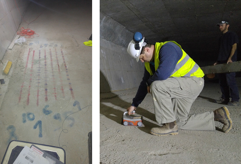
Figure 1. Mapping cable ducts layup using GPR.
The second step involves evaluation of wave velocity in the concrete slab, analysis of GPR data with duct position and structure design drawings in order to estimate at what depth air voids in cable ducts may provide sound reflection.
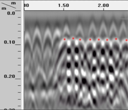
Figure 2. GPR map of ducts.
The third step is impact echo test itself, during which sound waves are induced using different diameter mechanical impactors, and acoustic reflections are detected and analyzed (Figure 3). In a concrete slab without ducts the frequency of reflection is inversely proportional to the slab thickness. In a case of completely grouted ducts, the distance of wave propagation is increasing and so effective thickness is increasing resulting in a small reduction of frequency. However, when a void is present, an additional reflection at a higher frequency corresponding to duct depth appears. In a case of empty ducts, the higher frequency reflection is even more significant (Figure 3).
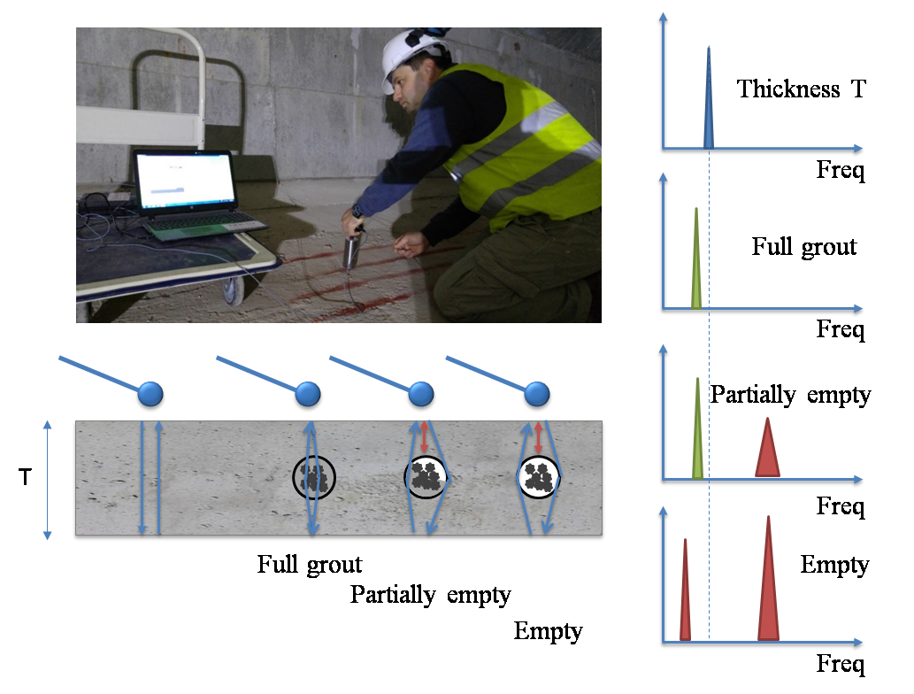
Figure 3. Illustration of impact echo duct inspection.
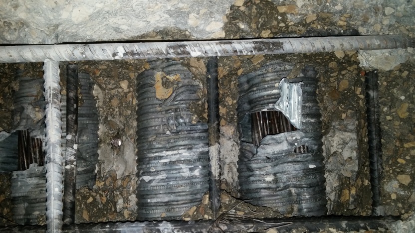
The final step in the inspection is validation of inspection results. Such validation can be performed not only in areas where indications for voids were detected but also in ducts that were reported as fully grouted (Figure 4). Validation can be performed by drilling small holes in the concrete and ducts or by concrete exposure using high pressure water cannon.
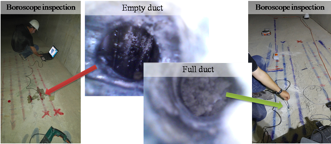
Figure 4. Validation of impact echo findings.
Impact Echo advantages
Impact echo technology has multiple advantages. Particularly, it allows:
- Non-destructive examination of cable ducts in new and in-services structures.
- Inspections from one side of the structure.
- High success rate.
- Short inspections times.
- Accurate measuring slab thickness.
- Detection of delaminations, cracks, honeycombing and other concrete flaws.